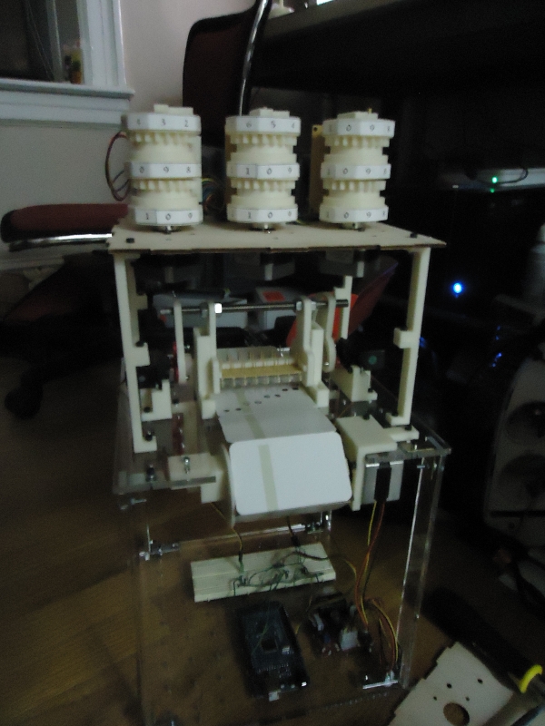
Behold the FIBIAC! Its loud! It computes! It uses actual punch cards! This is my first working incarnation of an idea for a simple electromechanical computer I’ve been playing around with for the last few years. I was initially looking for a practical project to bolster my non-existent mechanical engineering skills . . . it turns out an electromechanical computer is not actually a great ‘starter’ project for someone who’s never built anything with moving parts before, but it seems to have worked out well enough.
After trying out a number of ideas, I decided I wanted my machine to have a few key attributes:
- Minimize the use of ‘smart’ electronics. Doing things with digital logic is easy, and hence not nearly as much fun. Most of my hobbies boil down to engineering-with-one-arm-tied-behind-your-back.
- Have lots of moving parts (preferably loud ones).
- Use a chain of paper ‘instruction’ cards to program it.
- Actually be able to compute things on it.
I initially settled on a machine quite different from the one I wound up building. I was going to use an infrared-based, 35-bit (5×7 grid) card reader that could read black/white 1″ squares, and for storage, I would use a stack of floppy drives as single-digit, base-80 counters. It turns out that a floppy drive makes a terribly convenient base-80 counter, as it has a track-zero sensor, and the read head can be easily stepped up and down due to its built-in stepper controller. A floppy drive also costs about $1.50 on ebay, about 1/25 the cost of a typical stepper motor + driver. I actually spent a year and a half or so constructing a gargantuan card-reader, as well as an array of floppy drives (Wife: “Did you just buy a crate of floppy drives on ebay??”) before finally abandoning that path as 1) far too cumbersome for my 400 ft^2 apartment, and 2) far too limiting for computing things (1-digit, base-80 registers??!).
When I started this project, the only CNC tool I had access to for making parts was a laser cutter – something woefully inadequate for someone with my limited skills, it turns out. I finally acquired a Makerbot Thing-o-matic a few months ago, however, and I can’t recommend it enough! It’s just ridiculously easier to prototype with than anything I’ve worked with before (I literally redesigned the card reader 12 times before I got a reliable design!). In the end, ~90% of the machine was either printed on my Thing-o-matic or composed of parts from old Makerbots lying around at NYCResistor. When I decided to go the 3D printed route, I also managed to shrink the size of my instruction cards from 5″x8″ to business-card-sized (3.5″x2″), making things much more small-apartment-friendly. I also figured out a way to use spring-loaded pins and punch-cards to read the instruction stream rather than my infrared card-reader, making the machine drastically simpler and getting rid of ~50% of the electronics it initially needed, as well as significantly upping the machine’s geeky street-cred.
The result? Equal parts Charles Babbage and Rube Goldberg, I present the FIBIAC! This is a (surprisingly successful) proof-of-concept machine to test my counter-based electromechanical computer idea. It’s sporting the following:
- 3 x 3-digit Registers (equivalent to nearly 30 bits of memory!)
- 32-signal (8×4) punch-card instruction format
- 12 instruction-card capacity (could be made arbitrarily large if I had an arbitrarily bigger desk)
- Runs at nearly 1 increment/decrement per second!
The Card Reader
This was a fiendishly difficult mechanism to get working reliably! In order to minimize the electronics needed, the 32 pogo-pins on the card reader are tied directly to the Enable and Direction signals on the stepper controllers of the counter registers. The copper plate beneath the card being read is split into two sections – one side is just a grounded plate (to control the stepper controllers), the other section acts as a wired-OR gate, OR’ing together the selected zero-detect signals for each register.
Servos with neat little cam mechanisms are used to raise/lower the pogo-pin array while the card chain is being advanced/read, so that the cards don’t snag the delicate pogo-pins. The holes are just made using a standard hole punch I got at Office Depot, so they are only 1/4″ in diameter – meaning my cards can’t have more than 1/8″ of positioning ‘jitter.’ I fashioned a spring loaded bearing using a bent paperclip to make sure the card chain is always forced into position horizontally, and the vertical jitter is just handled by the stepper motor and square ‘rollers’ driving the card chain forward.
The pogo pins are arranged in a 4 x 8 grid with .4″ spacing, and soldered into a protoboard. I laser-cut a top and bottom plate out of 1/4″ acrylic to try to act as stiffeners and keep the pins straight (something surprisingly difficult to do, it turns out).
Below is a video of it running for the first time:
The Registers
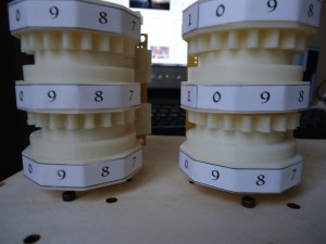
The heart of the machine is bank of electromechanical counters that make up its memory. Each of the three registers is an identical odometer-style, 3-digit, base-10 counter. A partially-toothed gear that straddles consecutive digits serves as a carry mechanism. The registers can be extended to arbitrary precision by just adding more digit wheels. Stepping the motor in one direction increments the counter, the other decrements it. Each digit-wheel also has a tiny magnet embedded in the face of it which trips a reed-switch whenever the digit is set to zero. All three reed-switches for the counter are wired in series, so that a signal gets grounded when the counter is set to 0-0-0. By means of punched-holes, I can select which register is connected to the system-wide ‘zero-detect’ signal that triggers the end of the current instruction.
If you’ve got a 3D printer, you can build your own!
How does it work?
All of the sequencing is done with a little microcontroller running the following algorithm.
1. Lower card-reader
2. Pulse steppers until zero_detect signal goes low.
3. Raise card-reader
4. Rotate card-advance mechanism 90 degrees.
5. Goto 1
As mentioned above, the ‘enable’ and ‘direction’ pins of the stepper motor controllers are wired directly to pins that will hit a grounded copper plate if a hole is punched in the right location. Three other pins let me select which set of registers I check to see if they’ve hit zero yet before continuing to the next instruction. My program to compute the fibonacci sequence looks like this:
- Enable R1, R3. Decrement R1, Increment R3. Stop when R1==0.
- Enable R1, R2, R3. Increment R1, Decrement R2, Increment R3. Stop when R2==0.
- Beep! (zero_detect is automatically grounded when buzzer and lamp are turned on)
- Enable R2,R3. Increment R2, Decrement R3. Stop when R3==0.
Since my program needed to be 12 instructions long in order to physically complete the loop, I just repeat the above sequence 3 times, and the program runs indefinitely. With more registers I could do fun things like multiplication or division, or something really awesome like computing the first three digits of pi!
See it in action!
Here it is in-action, computing the first few digits of the fibonacci sequence. The result shows up in the right-most register, and a lamp lights up (and a little buzzer beeps) whenever a new digit is ready. The machine is surprisingly reliable!
Future Plans
As I mentioned, this is more of a proof-of-concept than anything else. It has just enough registers to compute the fibonacci sequence, and doesn’t really support any control statements (you can do something not-quite-but-almost-like branch predication by OR’ing multiple zero_detect signals together, but that’s about it). My card reader has 32 pins though, just crying out for more computational goodness to be tacked on! It is actually designed to support the addition of a bank of 8 registers, and each register can be extended to arbitrary precision by just adding more digit wheels. The card reader also has space for a dedicated Jump register (think of it as an indirect pointer that could conditionally jump forward by n cards, and since each program is a physical loop, you only need to jump in one direction!), as well as an Input register and Output register, so one could actually make interactive programs, or log the output. The program could also be made arbitrarily long if I can ever figure out a mechanical method of accordion-folding the instruction chain (‘physical data compression’ . . . if you have any ideas, e-mail me!).
My main constraint at the moment is probably printing time. Each register takes 8 hours or so to print out (I probably had nearly 100 hours of total printing time to design and test all the parts for this). Perhaps I can spur a distributed manufacturing effort to pad out my register count (or I’ll just get bored enough to run my printer for 80 hours making counters). We’ll see what the future holds for this, but as a proof-of-concept, I’m now confident I could get a larger, more computer-like machine up and running without much more effort.

